| |
|
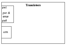
| pin | meaning |
| 1 | positve peltier terminal |
| 2 | positive powersupply 5.2 to 12V |
| 3 | negative peltier terminal |
| 4 | GND of powersupply |
| 5 | precision 2.5V and common of NTC |
| 6 | active NTC, on the regulated side |
| 7 | passive NTC, on the unregulated side |
| 8 | switched GND do not connect |
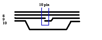
| pin | as RS485 | as RS232 |
| 1 | +5V out, can be omitted | +5V out, can be omitted |
| 2 | GND, reference for RS485 | GND, reference for RS232 |
| 3 | data+, bidirectional or tx only | nc |
| 4 | data-, bidirectional or tx only | nc |
| 5 | data+, rx only | nc |
| 6 | data-, rx only | nc |
| 7 | nc | Tx |
| 8 | nc | Rx |
| 9 | interlock, current in | interlock, current in |
| 10 | interlock, current out | interlock, current out |
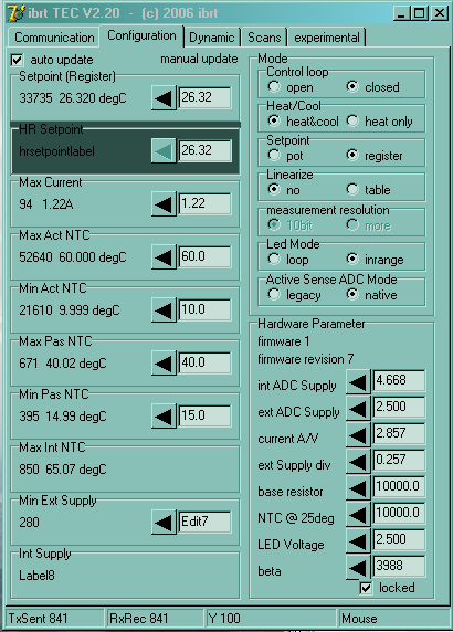
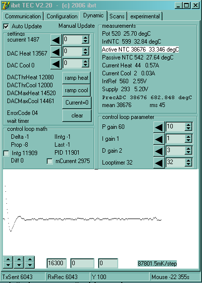
the following temperatures are monitored :
| sensor | compared for under temperature | compared for overtemperature |
| NTC on passive side of peltier element | MinPassiveNTC | MaxPassiveNTC |
| NTC on active side of peltier element | MinActiveNTC | MaxActiveNTC |
| NTC on the electronic | none | MaxIntNTC |